SirenSense — a project by Tekkera Electronix · tekkera.com

SirenSenseTekkera Electronix
  • CH1 north
  • CH2 east
  • CH3 south
  • CH4 west
bearing
137°
confidence
0.92
capture
44.1 kHz · 24-bit
i²s
GPIO 4/14 · 6/5

Hear danger.See it sooner.

Sirens are easy to miss from inside a modern car, and a warning you can only hear leaves people out. Three small devices turn what is happening around the vehicle into something you can see, hear and act on.

Designed, built and documented end to end by one engineer: the acoustic array, the firmware, the signal processing, the enclosure, the boards and this page. Every figure here is one this project earned.

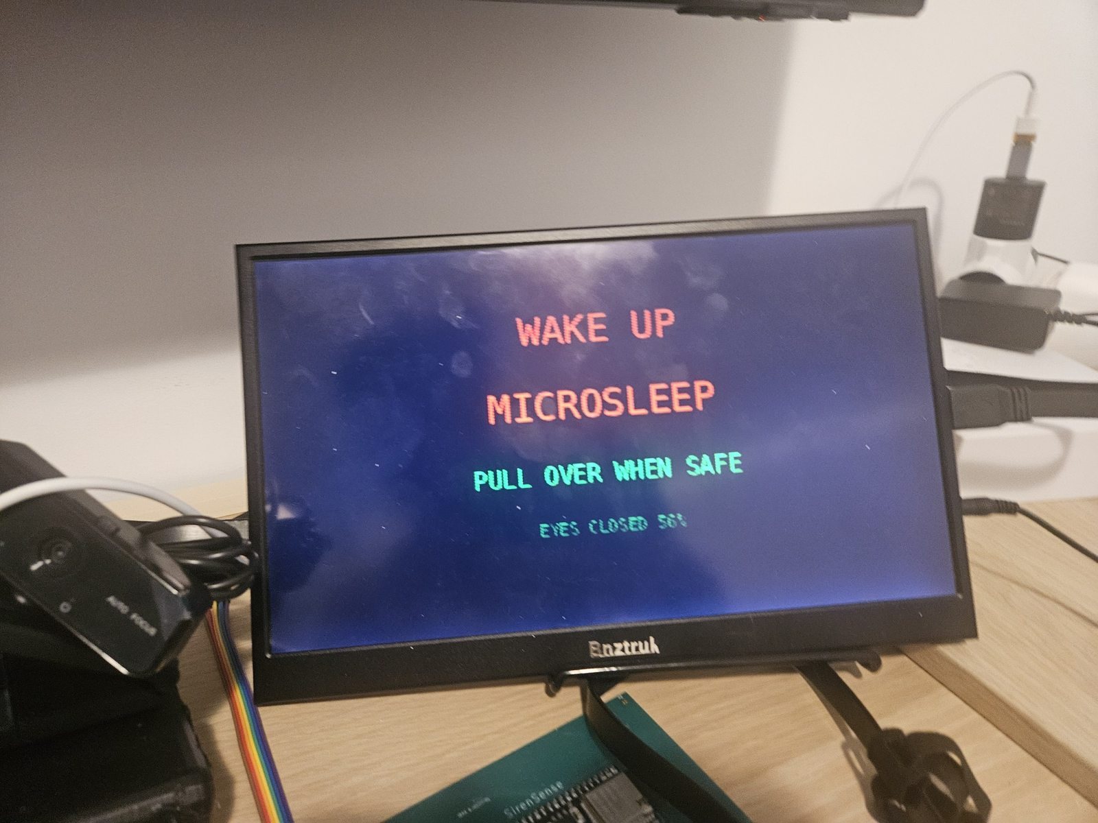
The SirenSense cabin node on a bench, its display showing a driver-monitoring alert that reads wake up, microsleep, pull over when safe, eyes closed 56 percent
How it looks when it is working: the cabin node raising a driver-fatigue alert on the bench. The microphone cross in the roof node is 190 mm across.
source
Hack4Change 2026 · first prize · ETSII, Universidad de Sevilla
built by
Ibrahim Najjar · Tekkera Electronix. One engineer, start to finish — concept, hardware, firmware, DSP, enclosure and site.
status
Research prototype. Not a homologated automotive product. V16 Pro is not DGT certified.

A second pair of ears, and a second pair of eyes

Sound insulation, music and closed windows all hide an approaching siren. And a warning that only makes a noise leaves out anyone who cannot hear it. SirenSense is a set of three small devices that turn the world around the car into something visible, spoken and directional — and listening for sirens is only one of the things it does. Everything in this section is meant to be understood without any mathematics. That begins further down the page.

Roof node

It listens

Four microphones in a cross, mounted outside the cabin where the road can actually be heard. It decides whether a siren is present, and which direction it is arriving from.

  • Gives a direction, not just a presence
  • Tells sirens apart from traffic, wind and road noise
  • Talks to the cabin over a short-range radio link
  • Runs from a single rechargeable cell

Cabin node

It shows and speaks

A small screen with one camera facing the road and another facing the driver. It shows the warning, says it out loud, and keeps the rest of the drive in one place.

  • Visual and spoken siren warnings
  • Dashcam and driver-facing camera
  • Maps that work with no phone signal
  • Vehicle data, air quality and motion

Transponder

It answers back

Carried by the emergency vehicle itself. It broadcasts its own position, so a nearby car can be told where the ambulance is instead of having to infer it from sound alone.

  • Adds a direct position channel
  • Long-range radio at 433 MHz
  • Position from satellite navigation
  • Encrypted position payload

What it actually does

Siren detection is one feature out of twelve. Each carries a status describing the project as it stands today: implemented means working in the prototype or its software, in integration means built but not yet proven in a vehicle, and concept means a designed direction that is not presented as a certified product function. A label changes only when the matching test is complete.

Siren detection

A small on-device AI model listens for sirens and tells them apart from traffic, music and wind. It was trained on real roadside recordings rather than clean studio samples.

Implemented

Which way it is coming from

The four microphones work together to produce a bearing, so a warning can say left, right, ahead or behind instead of only announcing that a siren exists.

Implemented

Dashcam

The front camera records the road ahead, with an interface built for full high-definition capture at 30 frames per second.

In integration

Driver monitoring

A camera facing the driver looks for signs of fatigue, distraction and phone use, and raises a warning rather than a score.

In integration

Pre-collision warning

Forward radar measures the distance and closing speed of the vehicle ahead, and warns when that gap is shrinking faster than it should.

In integration

Cabin environment

Air quality, humidity and temperature are measured inside the car — useful to the driver, and a way to protect the electronics from their own enclosure.

Implemented

Impact and motion

An accelerometer and a gyroscope record how the car is actually moving, and can flag a collision event alongside the surrounding video.

Implemented

Offline navigation

A vector map drawn by the device itself, so navigation and the emergency-vehicle display keep working with no phone signal and no cloud map service.

Implemented

Vehicle data

The interface reads the car's own diagnostic port (OBD‑II) and shows gauges and system health beside the safety alerts.

In integration

Emergency transponder

Long-range radio plus satellite position gives a participating emergency vehicle a direct line to nearby SirenSense units, naming where it is rather than merely that it exists.

Implemented

V16 Pro mode

A prototype emergency mode that shares its own position with nearby units and lights the roof beacon. It is not a regulatory replacement for a certified V16 device.

Concept · not DGT certified

Power and protection

Battery protection, charging, conversion and filtering are designed as part of the sensing chain rather than bolted on afterwards.

Implemented
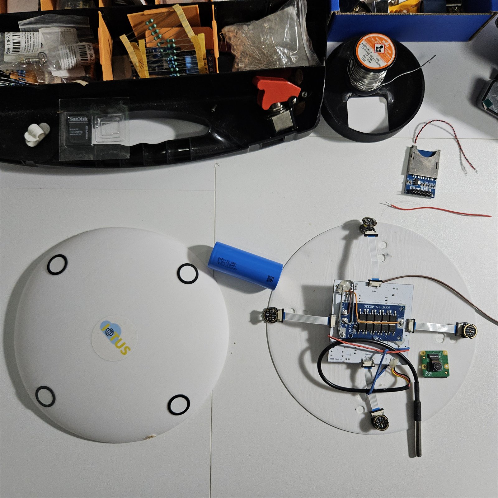
Two roof nodes side by side: the sealed unit with four round microphone ports in its lid, and an open unit showing the circuit board, battery, four microphone modules and satellite antenna
The roof node sealed and open: four microphone ports in the lid, with the cell, the board and a satellite antenna inside.
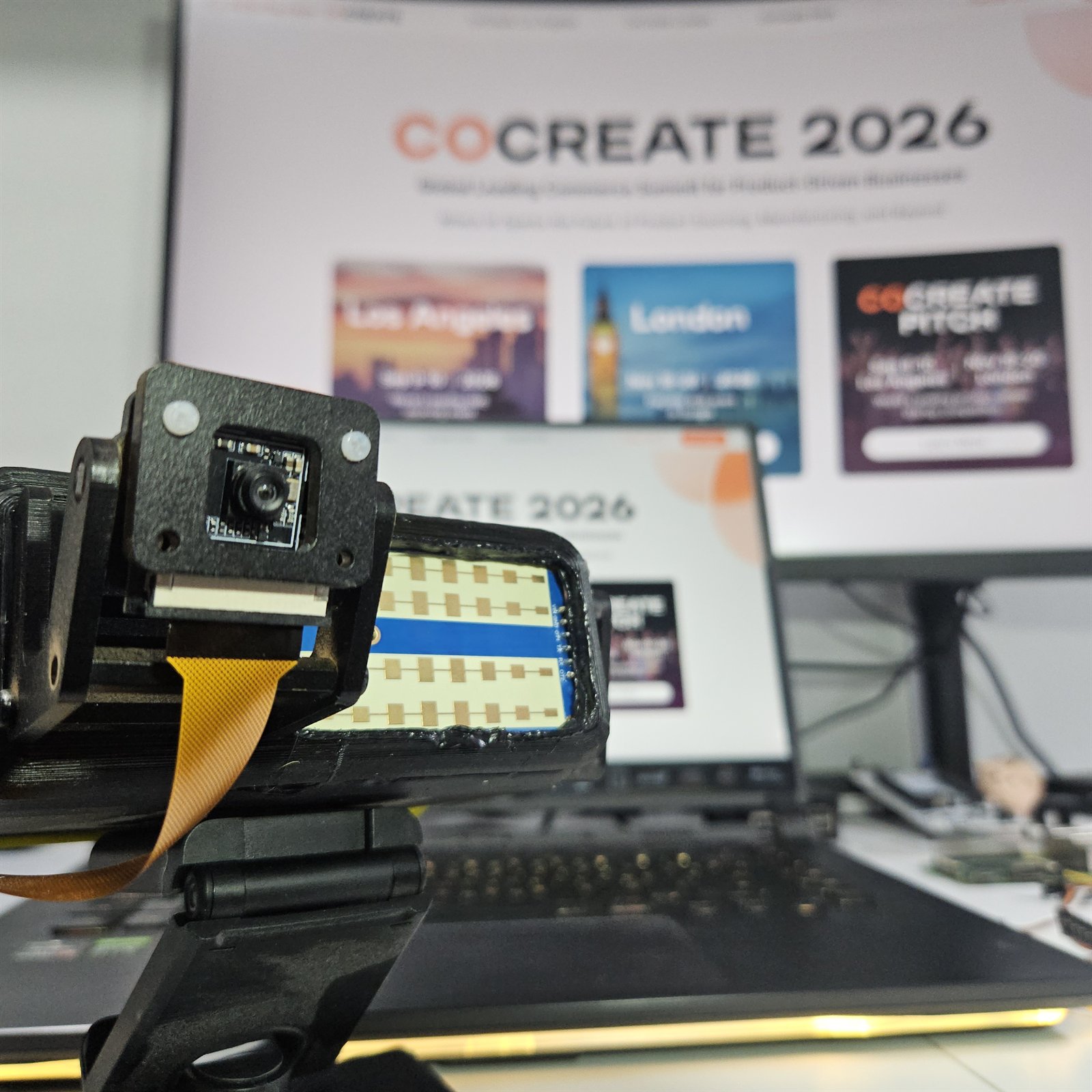
A camera module held in a printed bracket with its ribbon cable and connector board
A camera module in its printed bracket, ready to face the road or the driver.
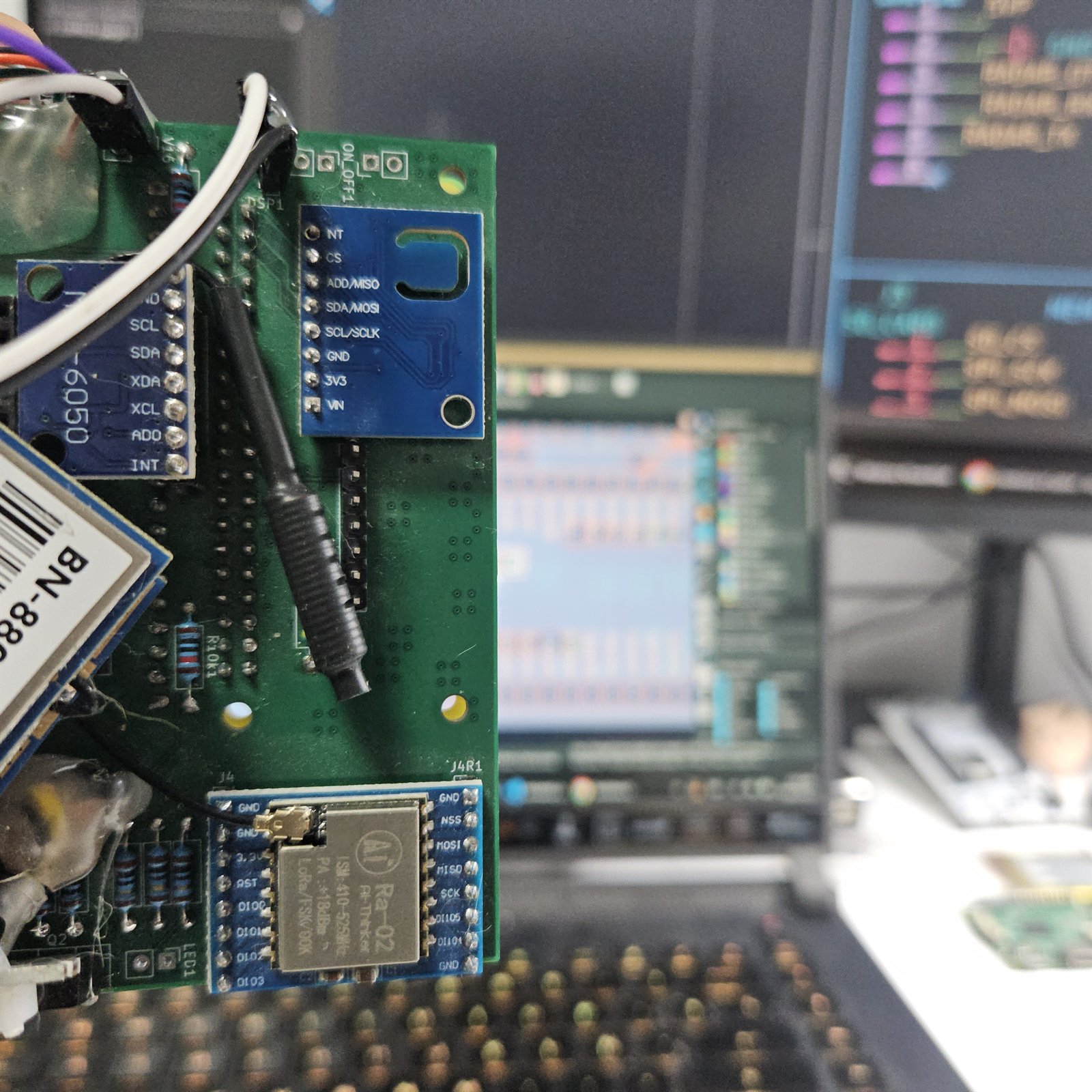
A circuit board carrying a BN-880 satellite navigation module, an MPU6050 motion sensor and a LoRa radio module
Position, motion and radio on one board: satellite navigation, a motion sensor and a long-range radio.

What is actually inside

The features above are not a list of ideas. Each one has a board, a module or a page of working behind it, and most of that work is a person at a bench with a notebook.

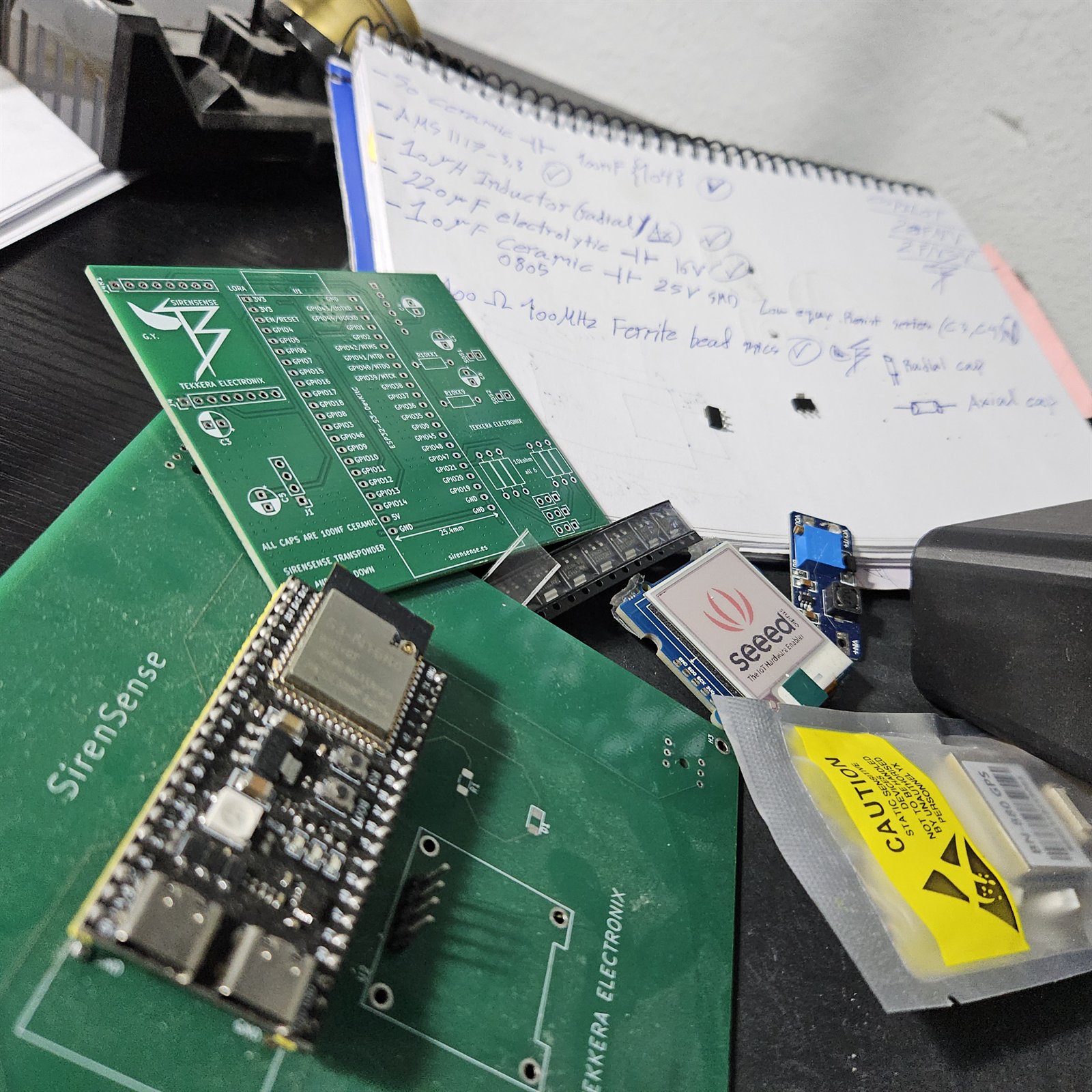
The green SirenSense transponder circuit board beside a long-range radio module, an ESP32 board and a handwritten list of power components
The transponder board with its long-range radio beside it. The notebook is the power list: regulator, inductors, capacitors and a ferrite bead.
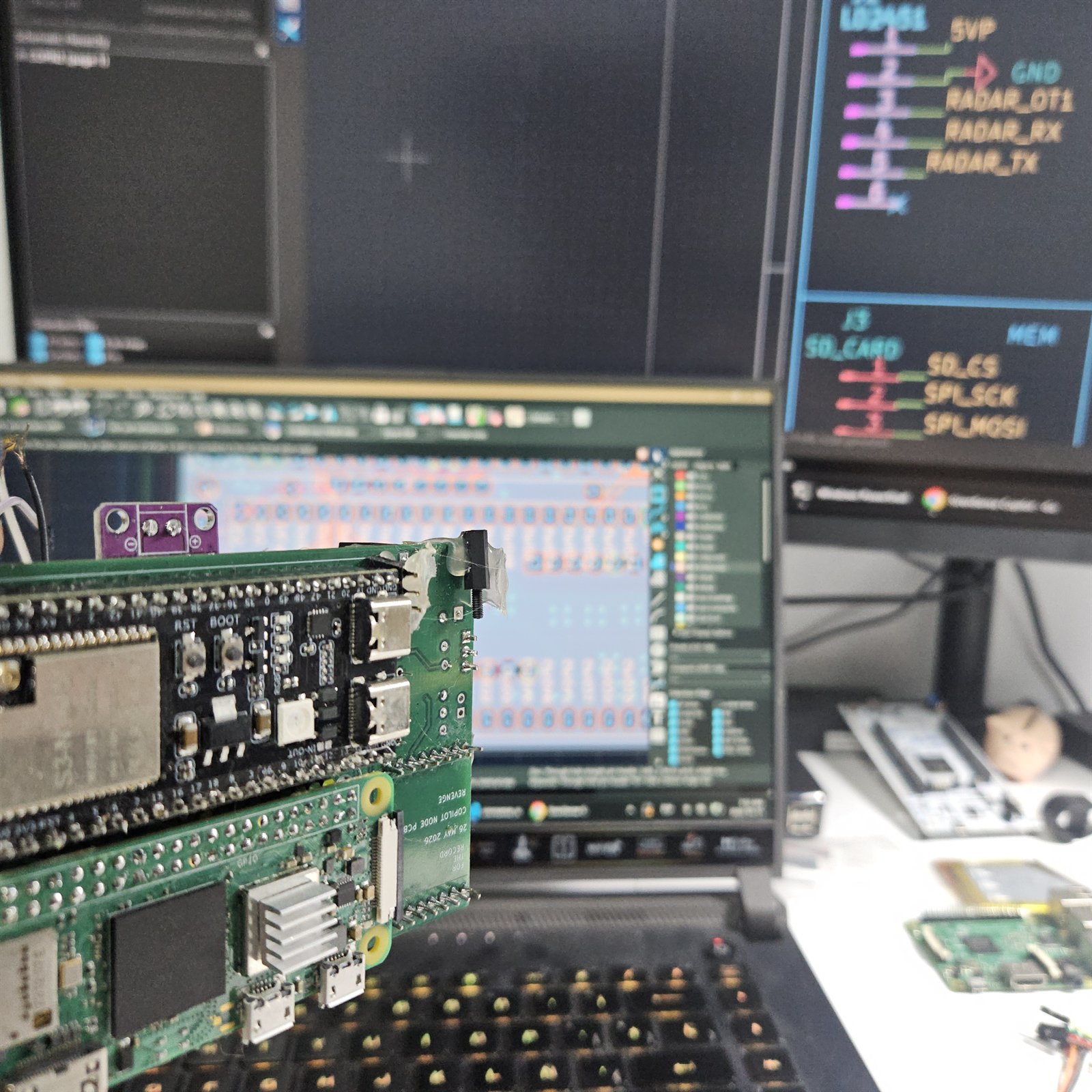
Several green SirenSense boards next to a laptop showing pin assignments for radar and for an SD card
Boards checked against the pin plan on screen, where the radar link and the SD card are assigned their own lines.
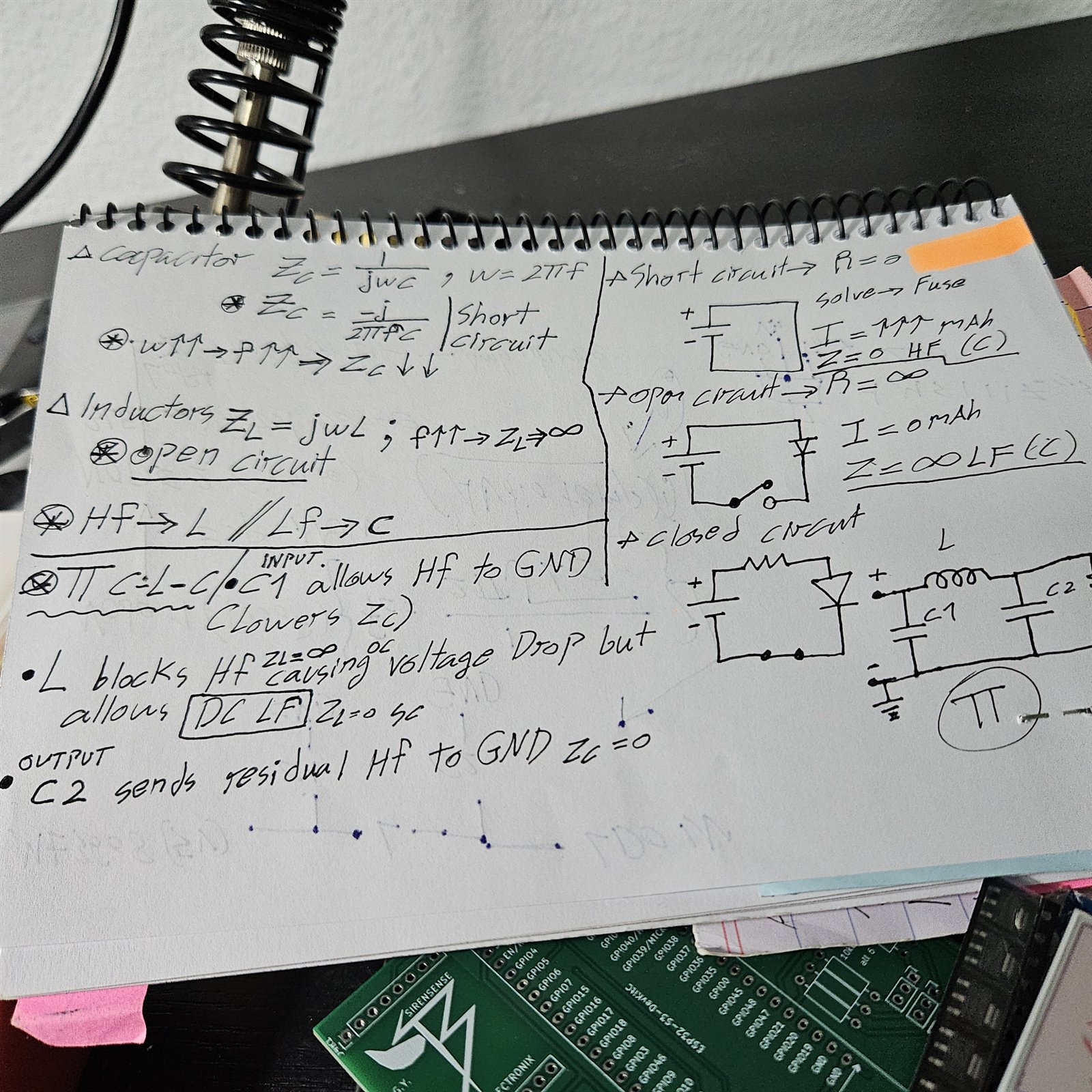
A page of handwritten engineering notes on capacitor and inductor impedance, with circuit sketches and a pi filter
Working the power filter out by hand: why an inductor blocks high frequencies while a capacitor sends them to ground.

How a siren becomes a bearing

Everything below follows from four numbers that are facts about this build: the 190 mm microphone cross, the speed of sound at 20 °C (343 m/s), the 44.1 kHz sample rate, and the 8× interpolation used on the delay estimates. Nothing here is a measurement of accuracy; that needs field characterisation this prototype has not finished.

Four microphones on a 190 mm cross with a plane wavefront arriving at bearing theta EW NS θ d = 190 mm

Time difference of arrival

A plane wavefront reaches the four microphones at different instants. The extra distance the wave must travel to the far microphone of a pair is the microphone separation projected onto the wave direction:

ΔxEW = d·cos θ   ΔxNS = d·sin θ

Dividing by the speed of sound gives the delay each pair measures:

τEW = (d/c)·cos θ   τNS = (d/c)·sin θ

The largest delay the array can ever see is therefore d/c = 554 µs, which at 44.1 kHz is 24.4 samples — comfortably inside the correlation window.

Delay measured by each pair against bearing angle, from zero to 360 degrees 0°90°180°270°360°+554µs−554 137° → τEW = −405 µs
FIG. 1 The two pairs measure quadrature sinusoids of the same amplitude, d/c = 554 µs. East–west is the cosine, drawn in the east ink; north–south is the sine, drawn in the north ink. Vertical gridlines mark the cardinal bearings; horizontal gridlines step 277 µs, a quarter of the 554 µs maximum. One 44.1 kHz sample is 22.68 µs, and near broadside that is worth 2.35° of bearing. The marker is the 137° worked example used throughout this page.

Two axes give one bearing

The delays are a vector: (τEW, τNS) has magnitude d/c and direction θ. Its angle is the bearing, so the two coordinates are combined directly:

θ = atan2(τNS, τEW)

At a true bearing of 137° the pairs read τEW = −405 µs and τNS = +378 µs, and atan2 returns 137°. Both delays scale with the speed of sound, so it divides out of the ratio — which is why the design does not claim that temperature compensation improves the bearing. Correcting c changes both axes by the same factor and the angle is unchanged.

A single pair alone cannot do this. It measures one delay, which is consistent with two opposite bearings, and its sensitivity collapses toward endfire.

The delay plane: the two measured delays form a vector of magnitude d over c, whose angle is the bearing θ τEW τNS −405, +378 d/c = 554 µs
Bearing error relative to a one-sample delay error, for a single pair and for the cross array 0°90°180°12×9×6×3×1× one pair: error → ∞ at endfire cross array: flat at 1×
FIG. 2 Relative bearing error for the same delay uncertainty, as a multiple of the cross array's own error. A single pair (ochre) degrades as 1/|sin θ| and is unusable at endfire; the curve is clamped at 12×. The cross (blue, dashed) holds a constant first-order error because when one axis is at endfire the other is at broadside: σθ = στ·c/d. Because that value is the reference, the dashed line is 1× by definition. With one sample of delay uncertainty it is 2.35° at every bearing; with 8× interpolation on the delay estimate it is 0.29°. That figure is the delay-grid resolution, not a measured angular accuracy — enclosure acoustics, reverberation, geometry and calibration set the real error.

Place a siren and watch the array locate it

Click anywhere in the scene to put an ambulance on the road. Every number below — the four channel delays, the pair delays, the correlation peaks, the bearing — is computed from where you clicked using the geometry above. Nothing is pre-recorded. Each panel states whether it is computed or a stand-in.

Click anywhere in the scene — or use a bearing button.

The array is drawn magnified: the real cross is 190 mm across, the car about 4.5 m. Scene scale is 40 px per metre.

  1. Siren emits
  2. Wavefront reaches the array
  3. Four channels capture
  4. Mel features
  5. Classifier fires
  6. GCC-PHAT peaks
  7. atan2 gives the bearing

Measured at the array

azimuth θ
—
range
—
τEW
—
τNS
—
delays
—
first arrival
—
Siren detected —

Four channels computed

The same burst reaches each microphone at a different instant; the spread is the real delay from your click, at true scale — not exaggerated.

Mel frame illustrative

Mel-spaced energy across one analysis window — the features the classifier consumes.

Classifier illustrative

A compact network over mel features returns a siren confidence, which gates whether a warning is raised at all.

GCC-PHAT correlation peaks exact

Whitening the cross-spectrum to phase alone sharpens the peak at the true delay. Peak positions are exact; the curve shape is a stand-in.

Bearing estimator src/main.cpp · public repo

/* get_siren_heading() — as it stands in the public repository */
for (int i = 0; i < samples; i++) {
    fl_e += abs(audio_FL[i]);  fr_e += abs(audio_FR[i]);
    rl_e += abs(audio_RL[i]);  rr_e += abs(audio_RR[i]);
}
/* energy to spatial pull */
float raw_x = (float)(-fl_e + fr_e - rl_e + rr_e);
float raw_y = (float)( fl_e + fr_e - rl_e - rr_e);

vector_x = (vector_x * (1.0f - DRIFT_FILTER)) + (raw_x * DRIFT_FILTER);
vector_y = (vector_y * (1.0f - DRIFT_FILTER)) + (raw_y * DRIFT_FILTER);

float final_rad = atan2(vector_x, vector_y);
int final_deg = (int)(final_rad * 57.2958f);
if (final_deg < 0) final_deg += 360;

Read this against the section above. The estimator in the public repository combines per-channel energy with atan2 and a drift filter: it does not compute time delays, and the string gcc_phat does not appear anywhere in that tree. Its channels are front–left, front–right, rear–left and rear–right, not the north–east–south–west cross described here. The delay-based path derived on this page is the documented design approach. Which of the two the current build ships should be confirmed before either is stated as fact.

Try the demo

Two interactive pages below run the same interfaces as the hardware. Nothing is a recording and nothing is pre-rendered: press a key and the display responds. Each page opens with a guided tour if you would rather be shown around, and every panel has a short explanation of what it does.

Both pages are simulations of the device interfaces, built so the system can be examined without the hardware present. Every function shown is implemented on the bench prototype. Nothing further is claimed: turn by turn navigation, blind spot radar, OBD-II telemetry and speed camera warnings are on the roadmap and are deliberately absent from these pages.

From four microphones to one warning

Detection and direction are separated on purpose. The classifier decides whether the window contains a siren at all; only then is correlation spent on finding where it is. That keeps the bearing pipeline off irrelevant audio.

4× INMP441 microphones

North, south, east and west on a 190 mm cross. Each pair shares one I²S data line by selecting the left or right slot of the stereo frame.

2× I²S in one clock domain

I²S0 (E/W, GPIO 4) is master and generates BCLK 6 and WS 5; I²S1 (N/S, GPIO 14) runs as a slave on those clocks through the GPIO matrix.

16 bits into the correlator

44.1 kHz, 32-bit slots, 24-bit microphone data; the correlation pipeline uses the top 16 bits.

MFE TinyML classifier

An Edge Impulse export with mel-filterbank energy features, trained on real roadside ambulance recordings with traffic, wind and Doppler — not clean online samples.

PHAT Delay estimation

GCC-PHAT whitens the cross-spectrum so only phase survives, giving a sharp delay peak that tolerates reverberation.

θ Bearing and a confidence gate

atan2 over the two axes gives the bearing; classifier confidence gates whether a warning is raised at all.

Why one clock domain matters

The two pairs never share a controller, so any assumed fixed offset between them is not a real delay. Subtracting one would inject a false delay into an axis, and near broadside the sensitivity is unforgiving. The build measured roughly 9° of bearing error from such a correction and removed it. Two I²S peripherals on one clock domain avoid the problem instead of compensating for it.

Rij(τ) = ∫ Xi(f) Xj*(f)|Xi(f) Xj*(f)| ej2πfτ df

Generalised cross-correlation with phase transform. Dividing by the magnitude discards amplitude and keeps phase, which sharpens the peak at the true delay τ and makes the estimate far less sensitive to reverberation than a plain cross-correlation.

Three phases, photographed as they happened

The prototype was not assembled in one go. It ran on breadboards, then moved to a first fabricated board in a printed enclosure, then to the working three-device system. The photographs below are in that order.

Phase 0

Breadboard bring-up

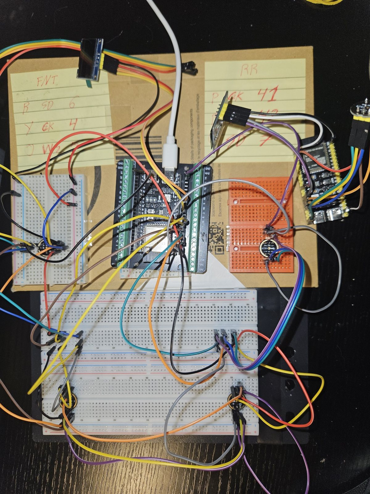
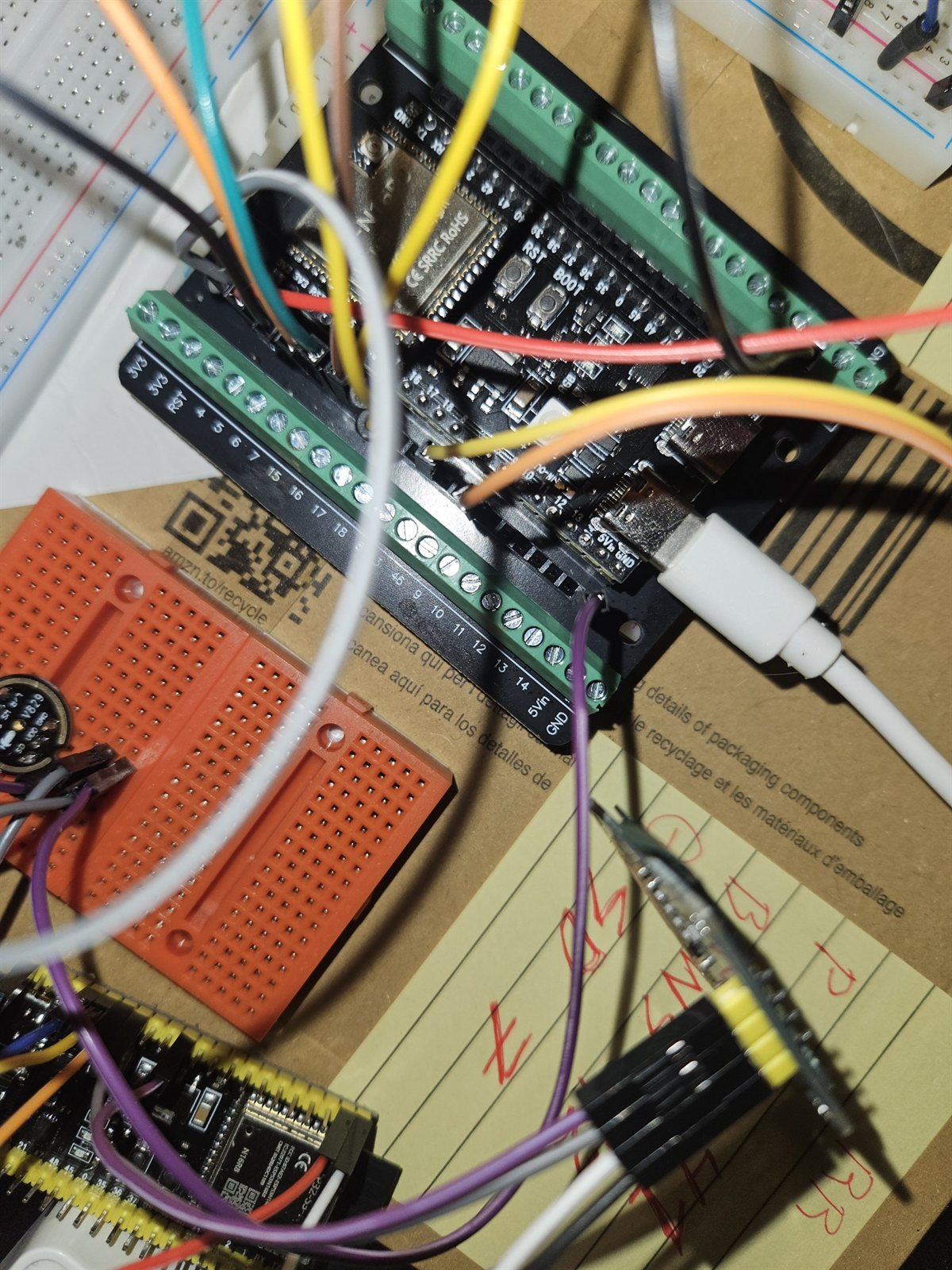
An ESP32-S3 devkit on screw-terminal carriers, two I²S microphones pairs wired by hand, and GPIO assignments written on paper because nothing was fixed yet. This is where the four-channel capture was first made to work.

Breadboards on cardboard wired to an ESP32-S3 devkit, with hand-written GPIO notes on yellow paper
Bring-up bench: hand-written wire and GPIO notes beside the first four-channel wiring.
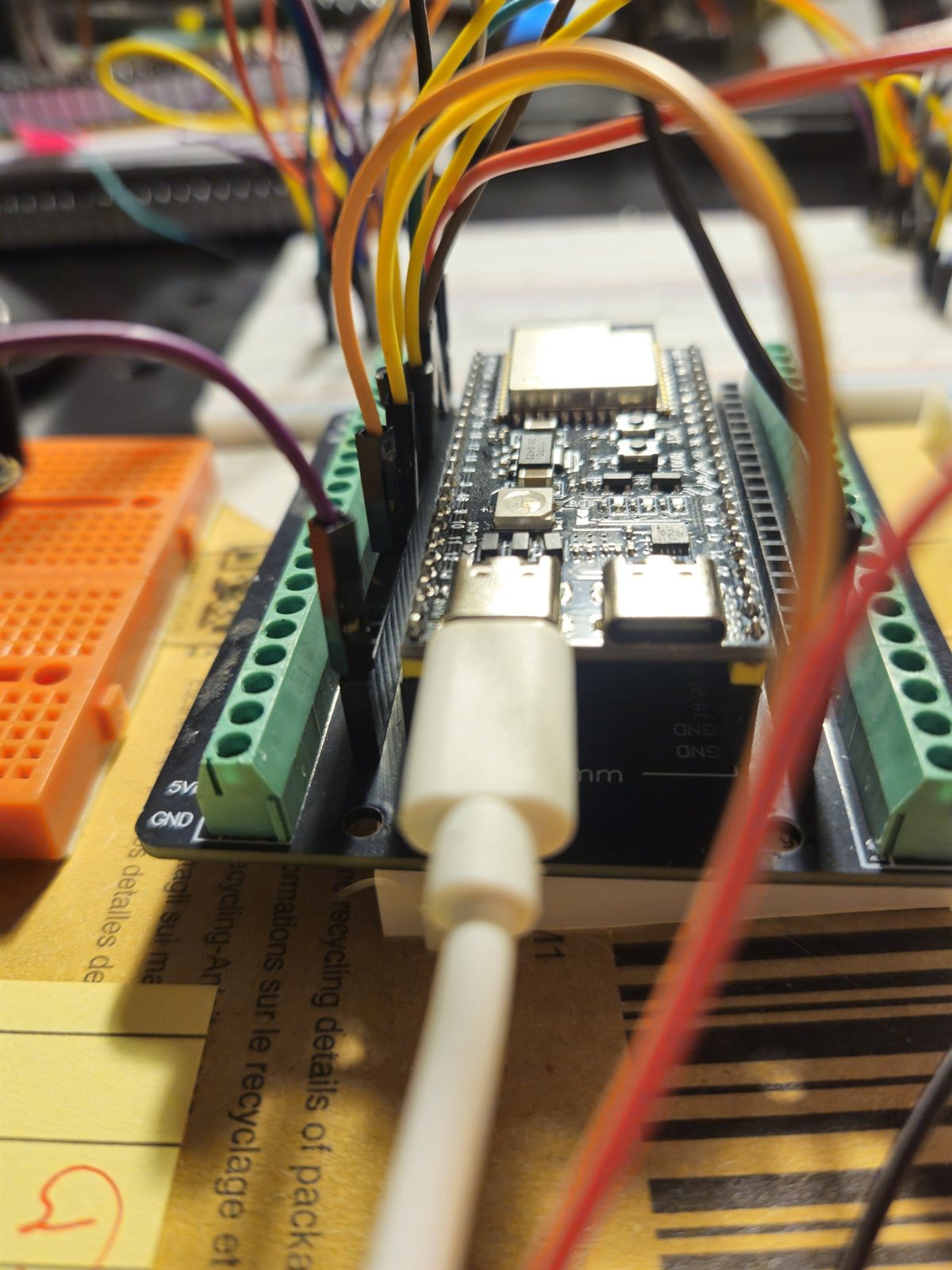
ESP32-S3 devkit in a green screw-terminal carrier with jumper wires
The devkit in its screw-terminal carrier, before any custom board existed.
Close view of the ESP32-S3 board with USB-C connected and wires leaving the terminal blocks
Power and signal leaving the carrier; the 5 V and GND rails are labelled on the block.
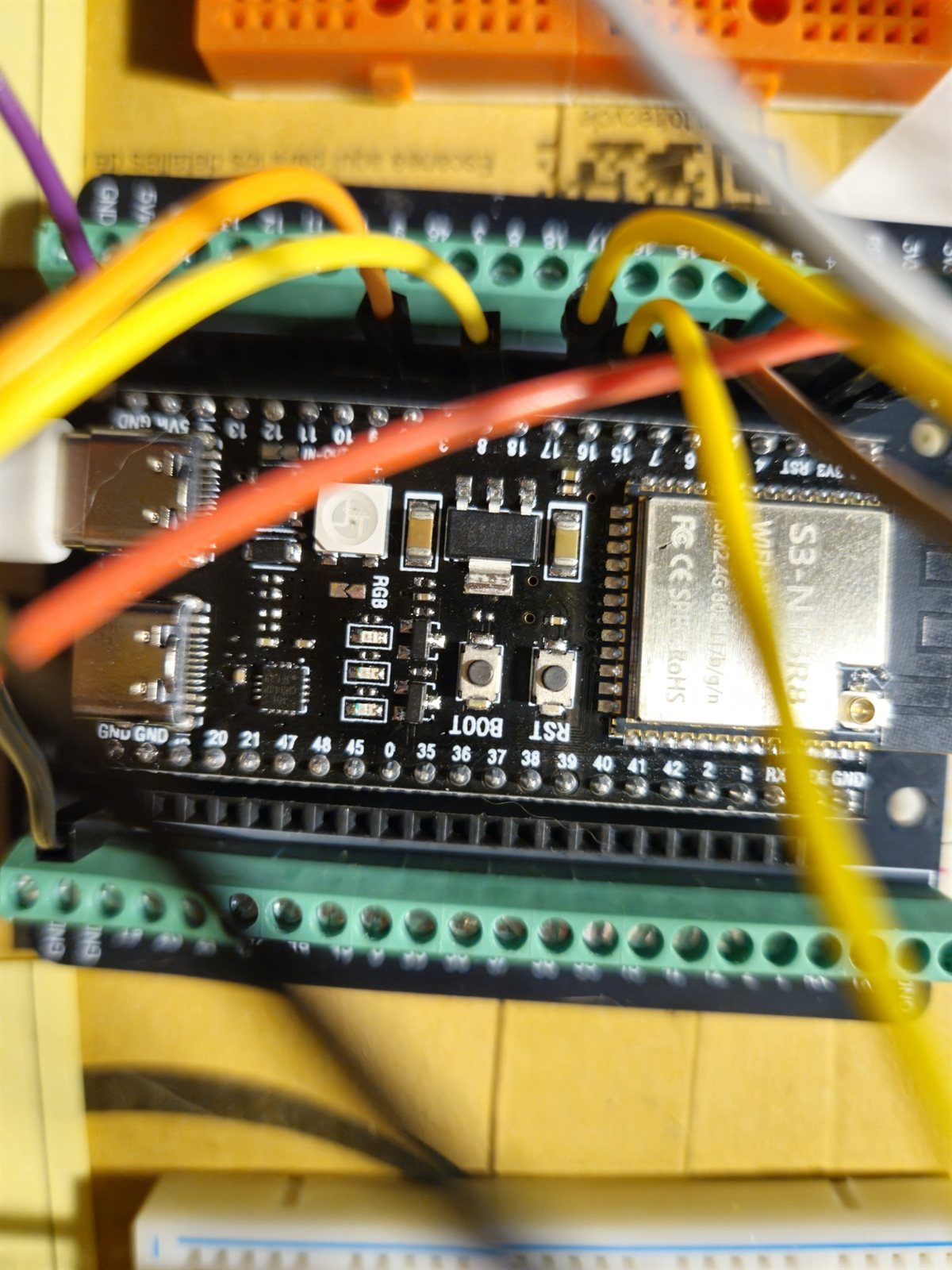
Macro photograph of the ESP32-S3-N16R8 module showing the BOOT and RST buttons and pin labels
ESP32-S3-N16R8 module: the MCU that runs all four channels.
Phase 1

First board, first enclosure

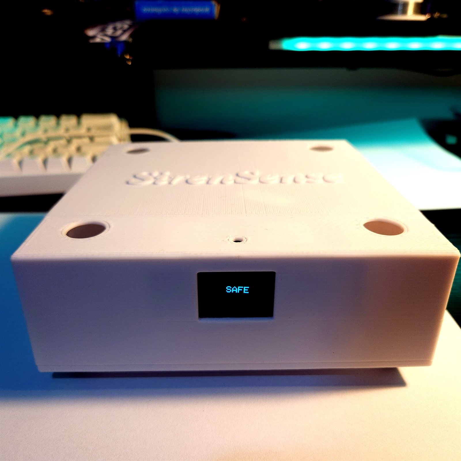
The hand wiring became a fabricated board carrying the same ESP32-S3, and the microphone cross got a printed housing with four ports in the lid. The silkscreen reads SirenSense · Tekkera Electronix · REV 1 · 04/2026.

A white printed enclosure with SirenSense embossed on the lid, four circular microphone ports and an OLED showing SAFE
The printed enclosure: four microphone ports in the lid and an OLED on the front face.
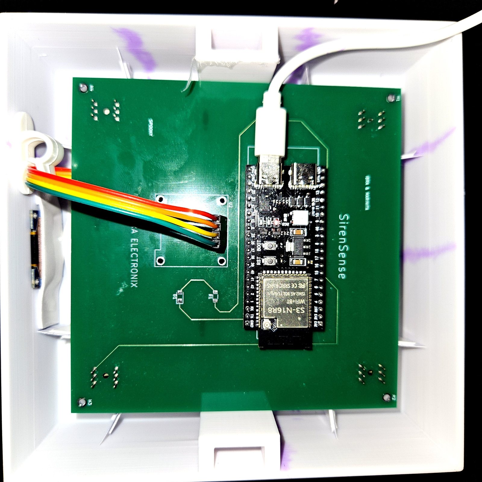
The green SirenSense REV 1 circuit board mounted inside the white printed enclosure
REV 1 board inside the enclosure, with the ESP32-S3 module seated on it.
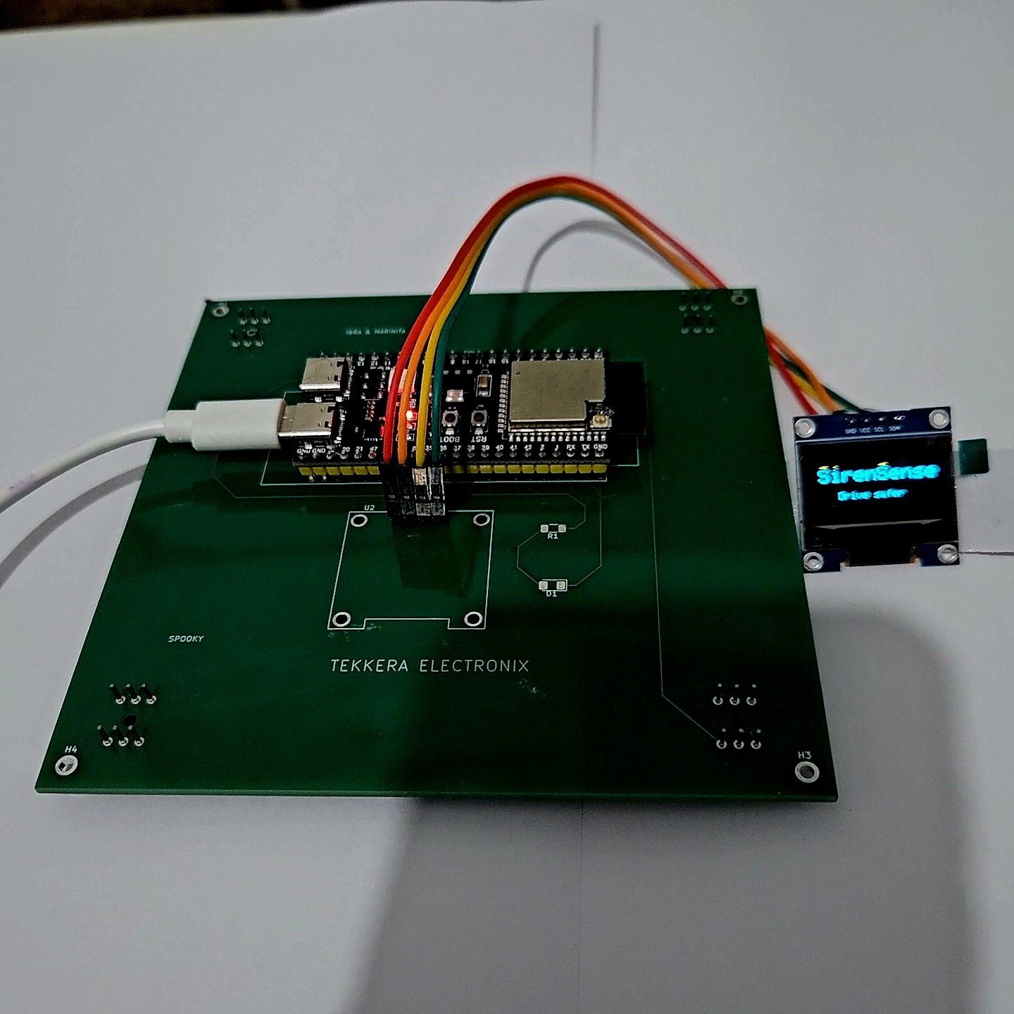
The REV 1 board on a bench with an OLED breakout displaying the SirenSense boot screen reading Oye antes
First boot screen on the OLED breakout: “SirenSense · Oye antes”.
Macro photograph of a lithium battery holder and small module with wires attached
Cell holder and supply wiring, before the roof-node power chain was assembled.
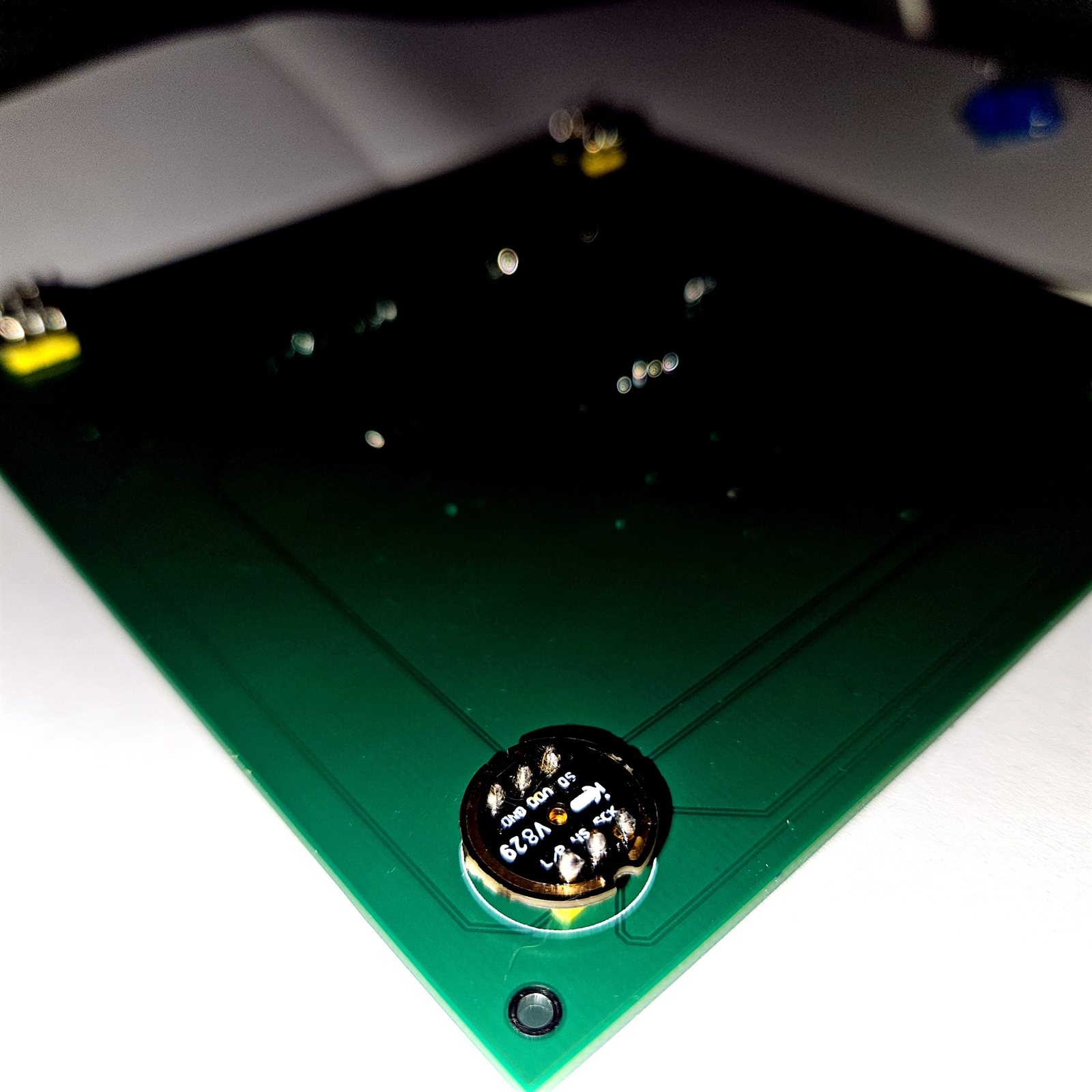
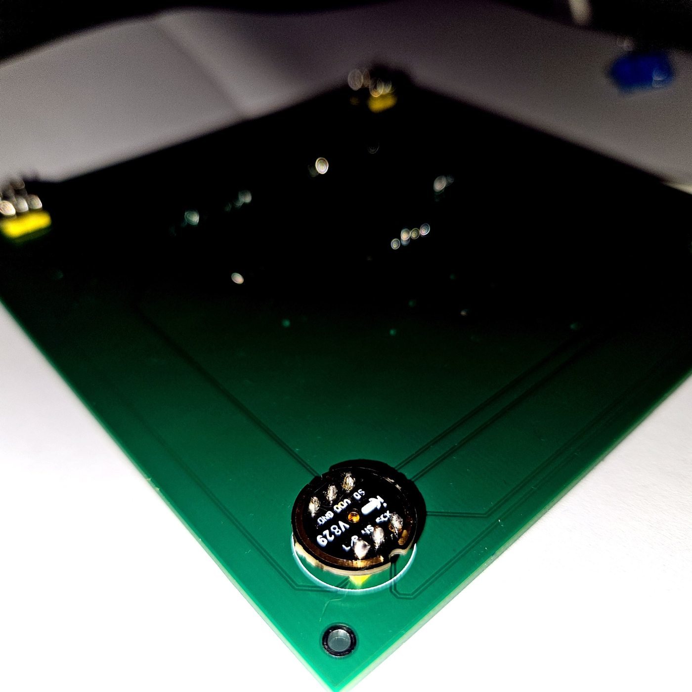
Low-angle close view of the green board showing the battery holder soldered on and copper traces
Board underside detail with the cell holder fitted.
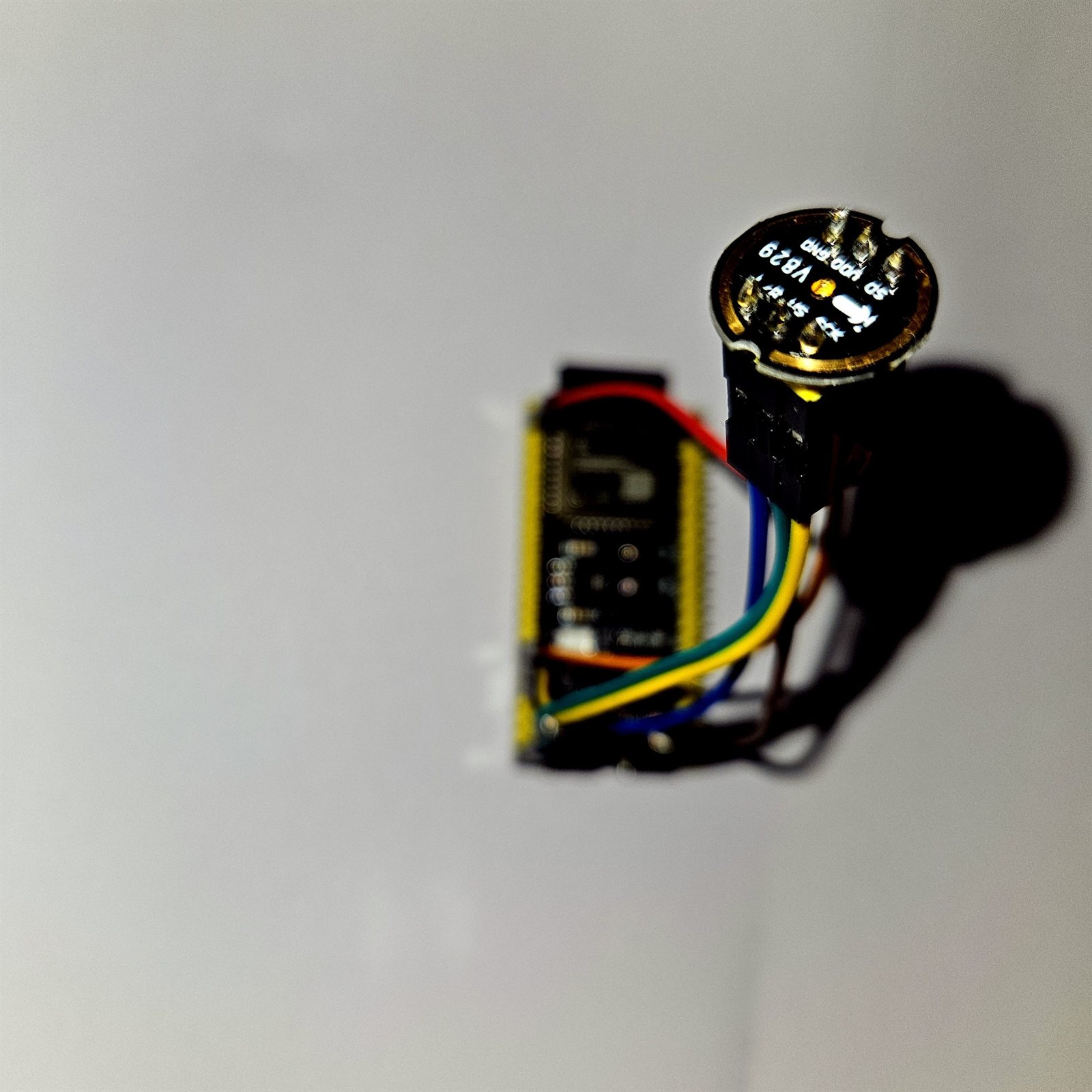
The custom four-microphone breakout board carrying the INMP441 microphones
The microphone breakout: one INMP441 per port in the lid, on a board cut for this enclosure.
Phase 2

The working three-device system

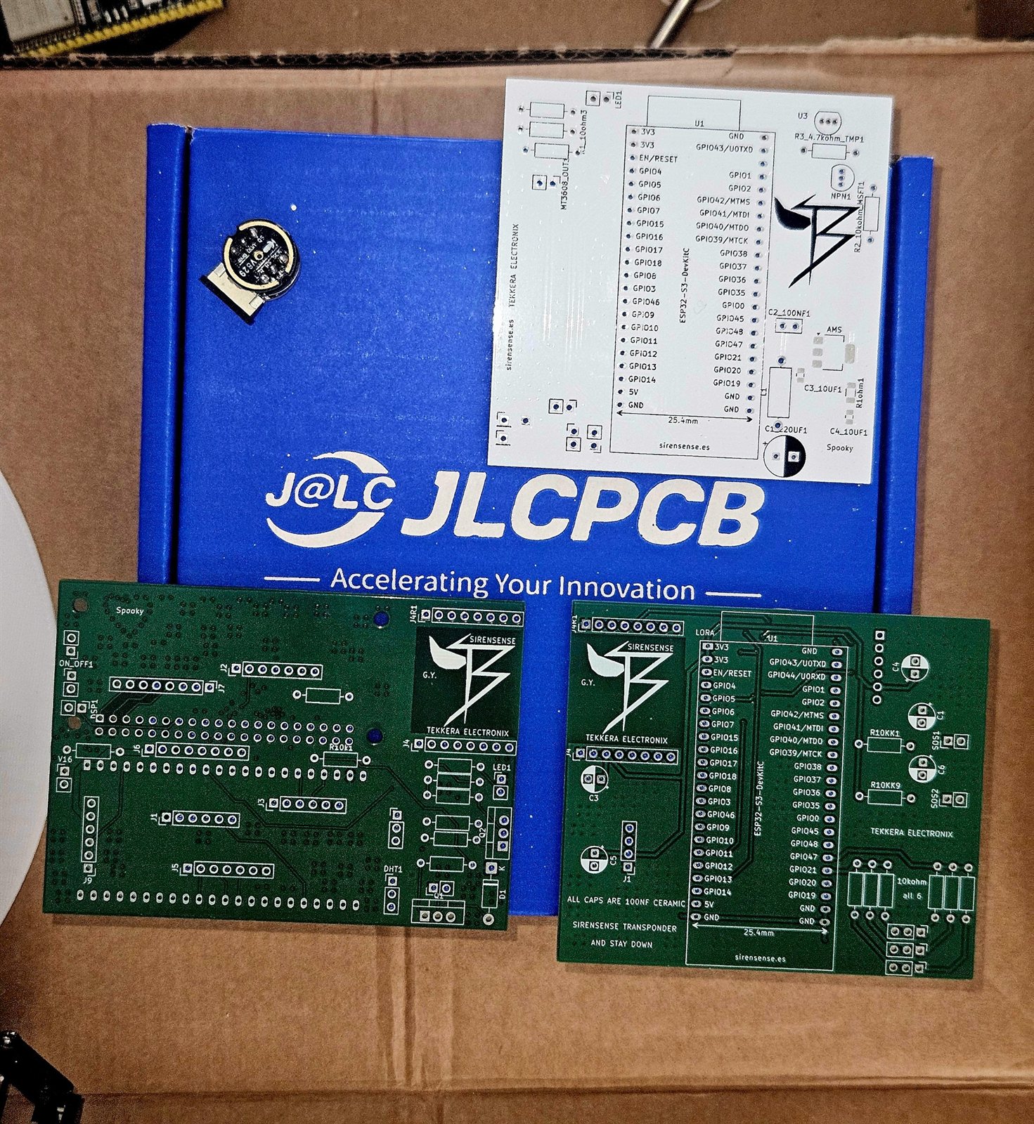
Fabricated boards from JLCPCB, the roof node's battery protection, the cabin node running its interface with camera and display, and the offline vector map. The cabin UI is shown reporting an emergency vehicle and the direction to expect it.

Three green fabricated circuit boards on a JLCPCB box, showing TEKKERA ELECTRONIX and SirenSense silkscreen
Fabricated boards: node, transponder and the “Spooky” board, all marked Tekkera Electronix.
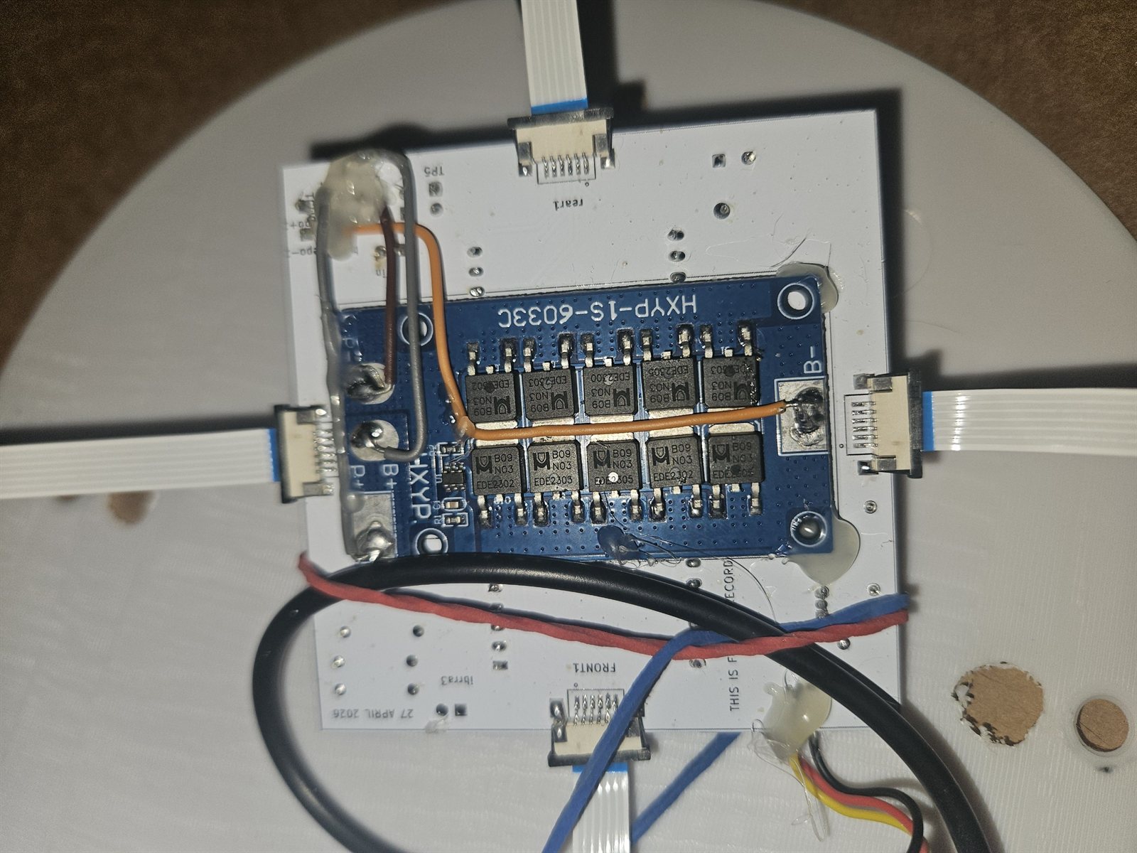
The interior of the roof node showing a blue HXYP-1S-60330 battery protection board with NCE3080K transistors and ribbon cables
Roof-node interior: the HXYP-1S-60330 1S protection board and its FETs, wired to the node board.
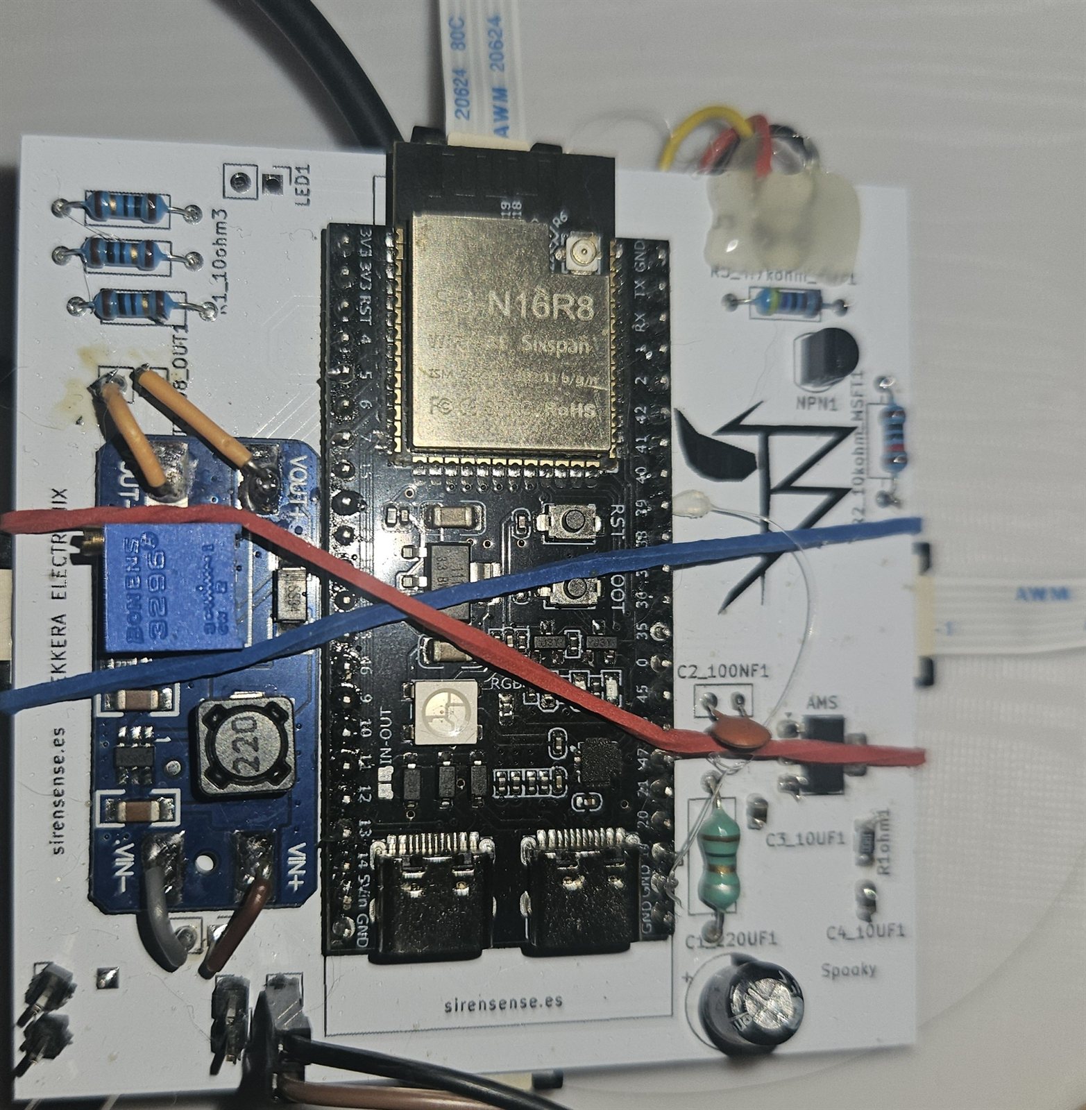
A white board with an ESP32-S3 module and passives under test, with test leads clipped on
Transponder board under test with probing leads attached.
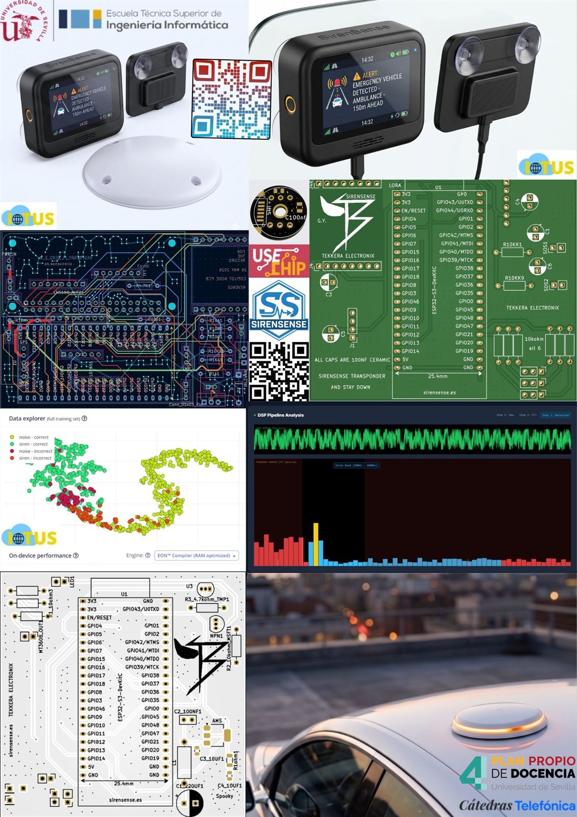
A project summary sheet combining the cabin device alert screen, PCB layouts, an Edge Impulse training-data scatter plot and the in-car view
Project sheet: cabin alert screen, both board layouts, and the Edge Impulse training-set explorer and DSP profile.
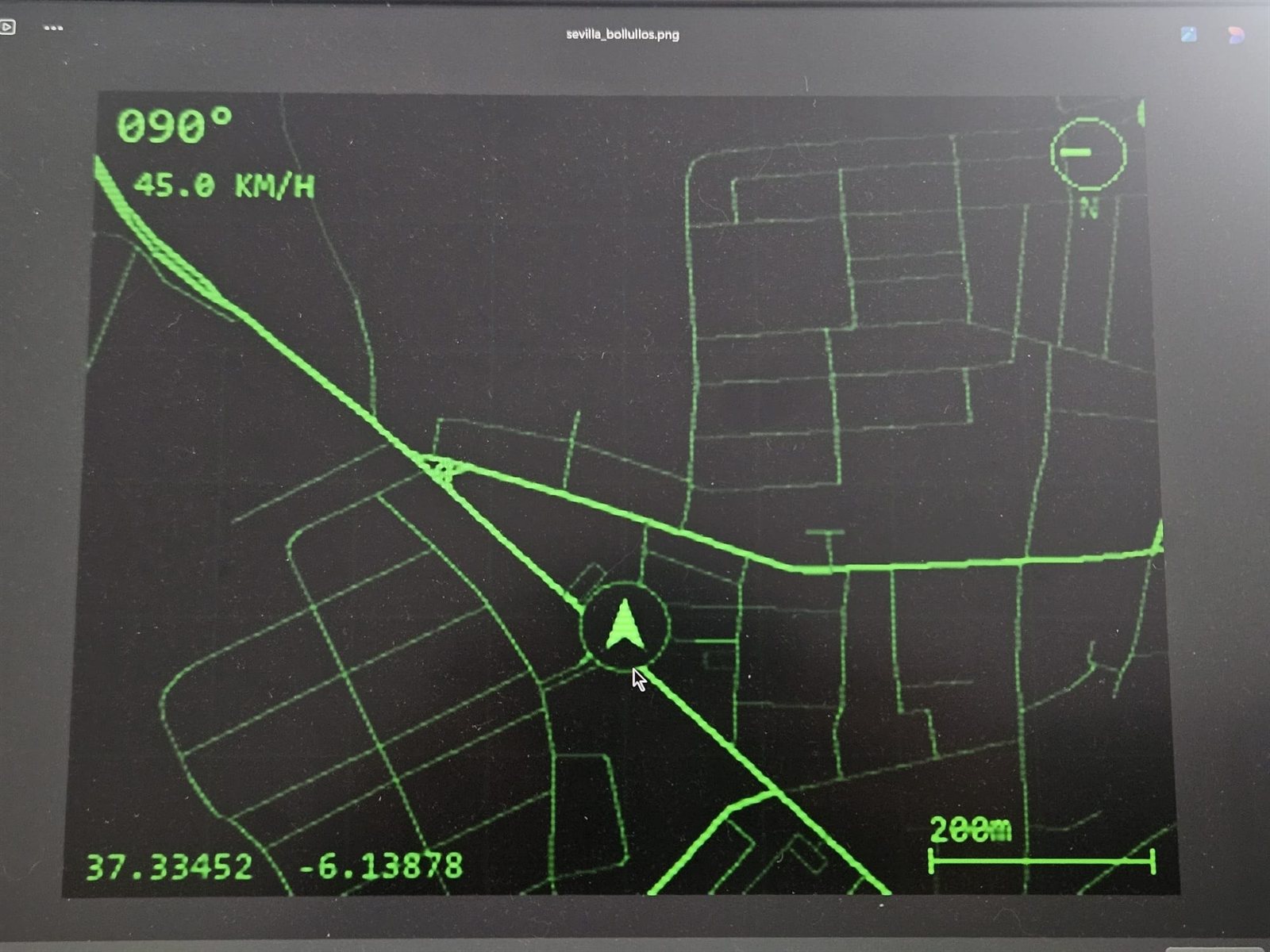
A dark screen showing a green vector map with a heading of 090 degrees, 45 kilometres per hour and coordinates
Offline vector map: heading 090°, 45.0 km/h, coordinates and scale, drawn without a cloud map service.
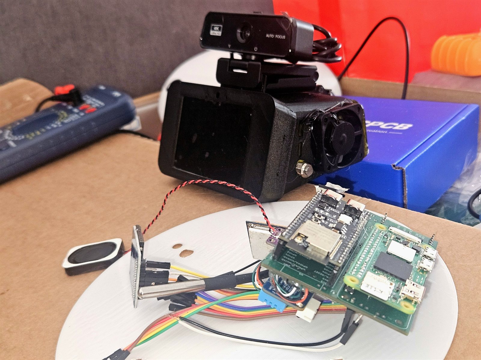
Bench test setup with a camera module, OLED, stacked green boards, a multimeter and a printed disc
Cabin-node bench test: camera, display, stacked boards and a multimeter on the same bench.

What is proven, and what is not

Status labels are part of the engineering, not marketing. They change only when the corresponding test is complete.

Four-channel synchronised captureImplemented, with startup loopback and calibration checks
Delay and bearing mathematicsDerived and implemented; the figures on this page are resolution, not measured accuracy
TinyML siren classificationWorking prototype; dataset expansion ongoing
Field bearing accuracyNot characterised — no single guaranteed number is claimed
Urban LoRa range4 km design target — not yet field-characterised
Weather resistanceIP67 sealing target — not independently certified
V16 ProA materially more capable evolution of the Spanish DGT V16 beacon concept. Not DGT certified; not a regulatory replacement for a certified V16 device

The notes behind the numbers

What the sections above compress into diagrams, written out: the pin map, the power chain, the cabin split and the transponder. Where a decision has a failure mode, the failure mode is stated with it.

Audio capture on the roof node

One ESP32-S3 captures all four channels; the array is not split across two controllers. An INMP441 can be told which slot of an I²S stereo frame to drive, so each opposing pair shares one data line, one microphone on the left slot and its opposite on the right.

East / WestI²S0 master · data GPIO 4
North / SouthI²S1 slave · data GPIO 14
Shared clocksBCLK GPIO 6 · WS GPIO 5 · routed internally through the GPIO matrix
Sample format44.1 kHz · 32-bit stereo slots · 24-bit microphone data
Correlator inputThe top 16 bits of each sample
Startup checkLoopback and calibration confirm both buses are alive and aligned
INMP441 E [L] ─┐
INMP441 W [R] ─┴─ DATA4  → I²S0 MASTER ─┐
                                BCLK6 / WS5
INMP441 N [L] ─┐                        │ internal GPIO matrix
INMP441 S [R] ─┴─ DATA14 → I²S1 SLAVE  ←┘

The second pair is a slave on clocks the first pair generates, rather than a second independent capture that would have to be aligned afterwards. The reason is in the pipeline section above: a fixed correction between independently clocked pairs is not a real delay, and applying one measured roughly 9° of bearing error on this build.

Detection gates direction

The classifier and the bearing estimator do different jobs and are not merged. The classifier is an Edge Impulse audio export using mel-filterbank energy features, trained on roadside ambulance recordings that include traffic, wind and Doppler shift rather than clean studio samples. Its confidence decides whether a window contains a siren at all.

Only windows that pass are handed to correlation. That ordering is what keeps the bearing pipeline off irrelevant audio, and it is why the simulator above labels its mel frame and classifier stage as stand-ins: the real model runs on the ESP32-S3 and this page does not pretend to reproduce it. False-positive behaviour on real roads remains an open dataset task, not a finished result.

Power integrity

The roof node keeps a radio, a switching converter and four digital microphones in one small enclosure, so the supply is part of the sensing problem rather than something downstream of it. The chain, in order:

  1. LiFePO₄ 26650 cell — the whole node runs from one cell.
  2. TP5000 USB-C module — charges on the LiFePO₄ profile, not a Li-ion one.
  3. 1S BMS — the protected system return is taken from P−.
  4. MT3608 boost converter — steps up to a regulated 5 V rail.
  5. π filter — 220 µF bulk, 10 µH series, 100 nF ceramic.
  6. AMS1117-3.3 — the microphone rail itself.
  7. Ferrite bead and 100 nF — at every microphone branch, not once at the supply.
  8. 12 V to 5 V adapter — a separate supply for the cabin unit.

Two ways to get this wrong

The MT3608 is a boost converter here, not a buck converter: the cell sits below the 5 V rail, so a step-down part would never regulate. And the protected return must come from the BMS P− terminal — taking it from B− bypasses discharge protection and defeats the protection circuit.

The cabin node, split in two

The cabin architecture separates time-sensitive I/O from the richer interface. Sensor reads and the radio link stay on a microcontroller; rendering, cameras and the application live on the Pi, and the two talk over a structured UART link.

ESP32-S3 controller

  • ESP-IDF v5 firmware
  • ESP-NOW messages from the roof node
  • LoRa, GPS, radar, audio, microSD and MPU6050 interfaces
  • Structured UART messages to the Raspberry Pi
  • Cabin PCB fabricated; assembly and complete bring-up in progress

Raspberry Pi application

  • Eight-page pygame interface
  • Siren alerts, offline vector navigation and system diagnostics
  • Front and driver-facing cameras
  • OBD-II gauges, media control through MPRIS and a rear-camera view
  • Managed as a Linux service with systemd

Keeping the time-sensitive path off a general-purpose operating system is the point of the split: nothing in the alerting chain depends on a desktop scheduler being in a good mood.

The emergency-vehicle transponder

A separate demonstrator, carried by the emergency vehicle itself. It broadcasts a compact position message that nearby SirenSense nodes can place on their map, so a warning can name a direction and a distance rather than a bearing alone.

ControllerESP32-S3
RadioSX1278 · 433 MHz LoRa
PositionBN-880 GNSS receiver
Local interfaceOLED status display
PacketAES-128 protected payload
Channel accessALOHA-style jitter, 800 to 1500 ms

A perfboard demonstration unit has been built and a PCB has been designed. Radio range has not been characterised in a controlled urban field test, so the figure carried in the register above — 4 km design target — not yet field-characterised — is an engineering estimate.

What these notes do not claim

The prototype has no IP certification. V16 Pro is not DGT certified and is not a regulatory replacement for a certified V16 device. No field bearing accuracy is stated, because none has been measured, and the classifier dataset is still growing. Each sentence changes only when the corresponding test is complete, in the register above.

The board layouts, the KiCad captures and the full validation register are on the technical record. Source and documentation: SirenSense and SirenSense V2 on GitHub.