σθ = στ · (343 m/s ÷ 0.190 m) = στ · 1805 s−1
What it computes
How an uncertainty in a delay measurement becomes an uncertainty in the bearing.
One pair first
Differentiating τ = (d/c) cos θ gives dτ/dθ = −(d/c) sin θ. Inverting it gives σθ = στ c / (d |sin θ|), which diverges as the source approaches endfire. That is the rising curve in FIG. 2, and the reason one pair is not enough.
Then the cross
With θ = atan2(τNS, τEW) the two partial derivatives are ∂θ/∂τNS = (cos θ) c/d and ∂θ/∂τEW = −(sin θ) c/d. Combining two equal, independent delay errors, and using cos² θ + sin² θ = 1, collapses the sum to
σθ = στ · c/d — the same value at every bearing
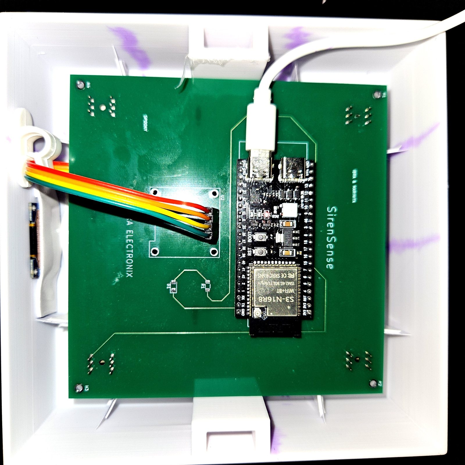
That identity is the whole argument for the cross geometry, and it is why the dashed line in FIG. 2 is flat rather than curved. Whichever axis sits at endfire, the other sits at broadside, and the two errors trade places exactly.
Symbols
| στ | uncertainty in a delay estimate, in seconds |
|---|
| c/d | 1805 s−1 — the conversion from a delay error to an angle |
|---|
| σθ | the resulting bearing uncertainty, in radians |
|---|
With real numbers
One sample of delay uncertainty is 22.68 µs. Multiplied by 1805 s−1 that is 40.9 mrad, or 2.35°. Interpolating the correlation peak 8× divides the delay step by eight and gives 0.29°.
What it does not tell you
This is a resolution figure, not an accuracy figure. It assumes the delay grid is the only source of error, and that the two axes are equally and independently uncertain. In a real enclosure, diffraction around the housing, reverberation, microphone mismatch and calibration error all contribute. This prototype has not been field-characterised, so no angular accuracy is claimed anywhere on this page.