Architecture without the marketing layer.
How the prototype is actually built, the decisions behind it, and the limits of what has been measured. This is a development system, not a certified automotive product. The bearing mathematics is derived on the overview page; this page is the record of the hardware and its status.
Built by one engineer at Tekkera Electronix — Ibrahim Najjar. Breadboards, boards, firmware, signal processing and enclosure all came from the same pair of hands.
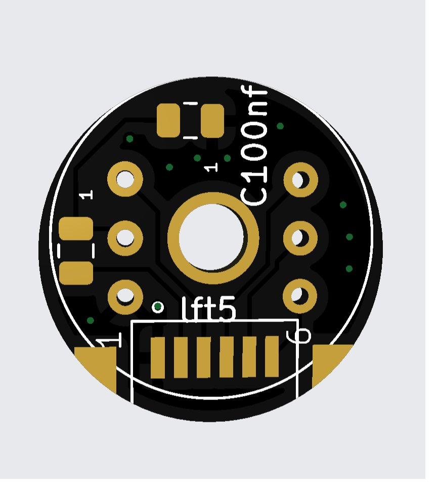
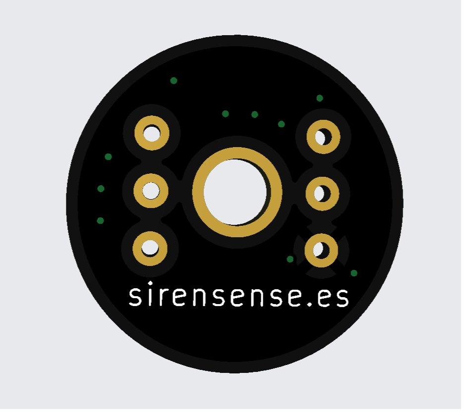
Four INMP441 microphones, one ESP32-S3
The array is not divided across two controllers. An INMP441 can be told which slot of an I²S stereo frame to drive, so each opposing pair shares one data line — one microphone on the left slot, its opposite on the right — and both pairs run on one clock domain.
| East / West | I²S0 master · data GPIO 4 |
|---|---|
| North / South | I²S1 slave · data GPIO 14 |
| Shared clocks | BCLK GPIO 6 · WS GPIO 5 · routed internally through the GPIO matrix |
| Sample format | 44.1 kHz · 32-bit stereo slots · 24-bit microphone data |
| DSP input | The top 16 bits of each sample, into the correlation pipeline |
| Startup check | Loopback and calibration confirm both buses are alive and aligned |
INMP441 E [L] ─┐
INMP441 W [R] ─┴─ DATA4  → I²S0 MASTER ─┐
                                BCLK6 / WS5
INMP441 N [L] ─┐                        │ internal GPIO matrix
INMP441 S [R] ─┴─ DATA14 → I²S1 SLAVE  ←┘
Why no fixed pipeline correction is subtracted
Each opposing pair is captured by the same I²S controller, so the two never share a controller across pairs. Subtracting an assumed inter-controller pipeline offset from either axis injects a delay that is not a delay. This build measured roughly 9° of bearing error from such a correction and removed it. Two peripherals on one clock domain avoid the problem instead of compensating for it.
Detection first, direction second
The classifier decides whether a window contains a siren at all; only windows that pass are handed to direction finding. That ordering is what keeps the bearing pipeline off irrelevant audio.
Audio classifier
- Edge Impulse audio export with mel-filterbank energy features
- Trained on roadside ambulance recordings with traffic, wind and Doppler shift, not clean studio samples
- Classification confidence gates the warning path
- Arduino/PlatformIO on the roof node to support the exported model
- Real-world false-positive testing remains an open dataset task
Direction finding
- Two delay axes, east–west and north–south, over a 190 mm cross
- One sample at 44.1 kHz is 22.68 µs, worth 2.35° near broadside
- 8× interpolation on the delay estimate gives a theoretical 0.29° delay-grid step
- 0.29° is resolution, not measured accuracy
Temperature, and what it does not fix
Correcting the speed of sound changes a distance or delay model, but both axes carry the same d/c factor and it cancels once they are combined with atan2. The design therefore does not claim that temperature compensation improves bearing accuracy. The derivation, with every symbol explained, is on the overview page.
Which estimator ships is unconfirmed
The delay-based bearing above is the documented design approach. The estimator as it currently stands in the public repository combines per-channel energy with atan2 and a drift filter, and the string gcc_phat does not appear anywhere in that tree; its channels are front–left, front–right, rear–left and rear–right rather than the north–east–south–west cross. Which of the two the current build ships should be confirmed before either is stated as fact.
The microphone rail is part of the signal chain
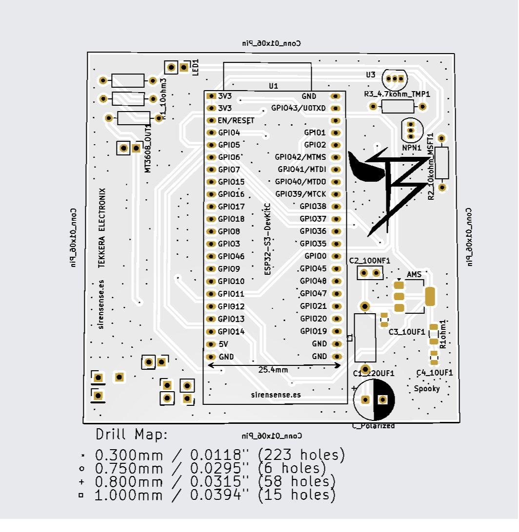
The roof node keeps a radio, a switching converter and four digital microphones inside one small enclosure. Battery protection, conversion and filtering were designed together rather than treated as an afterthought. The chain, in order:
- LiFePO₄ 26650 cell — the whole node runs from one cell.
- TP5000 USB-C module — charges on the LiFePO₄ profile, not a Li-ion one.
- 1S BMS — battery negative to B− only; the protected system return is taken from P−.
- MT3608 boost converter — steps up to a regulated 5 V rail.
- π filter — 220 µF bulk, 10 µH series, 100 nF ceramic.
- AMS1117-3.3 — the microphone rail, with a documented ESR arrangement.
- Ferrite bead and 100 nF — 100 Ω at every microphone branch, not once at the supply.
- 12 V to 5 V adapter — a separate supply for the cabin unit.
Two ways to get this wrong
The MT3608 is a boost converter in this node, not a buck converter: the cell sits below the 5 V rail, so a step-down part would never regulate. And the protected return must come from the BMS P− terminal — taking it from B− bypasses discharge protection and defeats the protection circuit.
Real-time controller beside a Linux interface
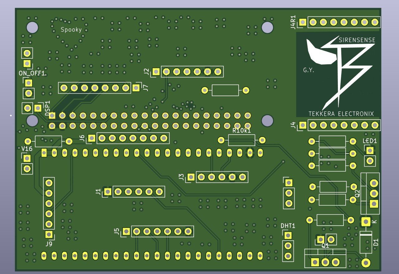
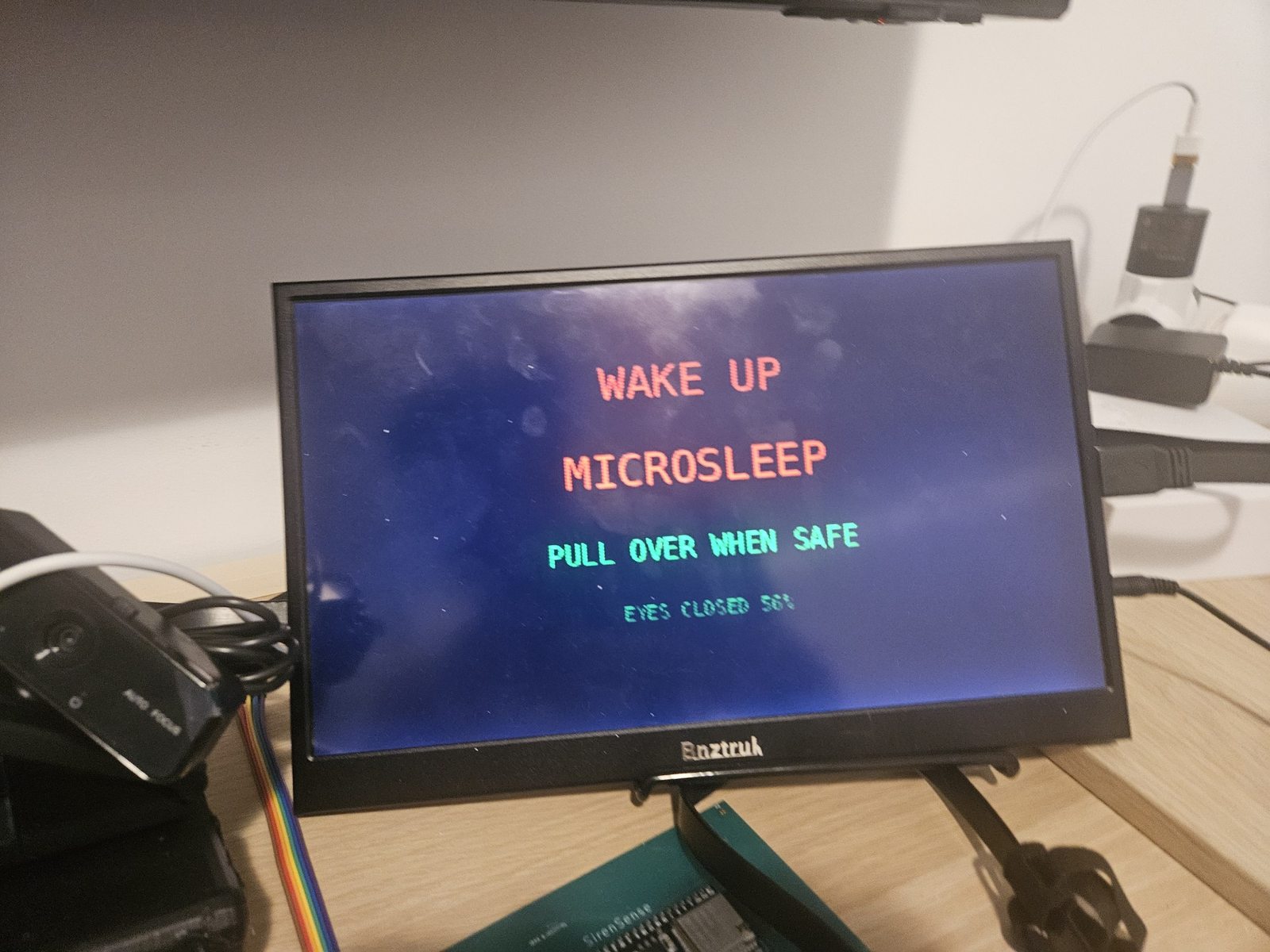
Time-sensitive I/O is separated from the richer interface. Sensor reads and the radio link stay on a microcontroller; rendering, cameras and the application live on the Pi, and the two talk over a structured UART link.
ESP32-S3 controller
- ESP-IDF v5 firmware
- ESP-NOW messages from the roof node
- LoRa, GPS, radar, audio, microSD and MPU6050 interfaces
- Structured UART messages to the Raspberry Pi
- Cabin PCB fabricated; assembly and complete bring-up in progress
Raspberry Pi application
- Eight-page pygame interface
- Siren alerts, offline vector navigation and system diagnostics
- Front and driver-facing cameras
- OBD-II gauges, media control through MPRIS and a rear-camera view
- Managed as a Linux service with systemd
Sensor correction
A DS18B20 connected to the Raspberry Pi did not enumerate during development, so the AHT21 is the current fallback source. The site does not claim two independently validated temperature sensors.
A direct position channel
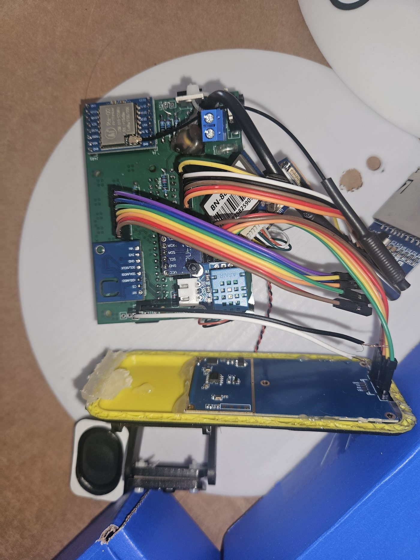
A separate demonstrator, carried by the emergency vehicle itself. It broadcasts a compact position message that nearby SirenSense nodes can place on their map, so a warning can name a direction and a distance rather than a bearing alone.
| Controller | ESP32-S3 |
|---|---|
| Radio | SX1278 · 433 MHz LoRa |
| Position | BN-880 GNSS receiver |
| Local interface | OLED status display |
| Packet | AES-128 protected payload |
| Channel access | ALOHA-style jitter, 800 to 1500 ms |
| Build state | Perfboard demonstration unit built; PCB designed |
| Urban range | 4 km design target — not yet field-characterised |
The radio range has not been characterised in a controlled urban field test. The figure above is an engineering estimate, and any response-time improvement it implies is an estimate for the same reason.
No silent jump from prototype to product
Clear status is an engineering feature, not a disclaimer. These labels describe the project today and change only when the corresponding test is complete.
| Roof-node PCB and enclosure | Built and demonstrated |
|---|---|
| Four-channel synchronised capture | Implemented, with startup loopback and calibration checks |
| TinyML siren classification | Working prototype; dataset expansion ongoing |
| Direction pipeline | Delay-based bearing derived and implemented as the documented design. The estimator in the public repository currently takes direction from per-channel energy with atan2. Which of the two the current build ships is unconfirmed |
| Field bearing accuracy | Not characterised — no single guaranteed number is claimed |
| Cabin PCB | Fabricated; final assembly and complete bring-up ongoing |
| Raspberry Pi interface | Working software; Pi 5 and in-car validation pending |
| Transponder | Perfboard demo built; production PCB and range tests pending |
| Weather resistance | IP67 sealing target — not independently certified |
| V16 Pro | A materially more capable evolution of the Spanish DGT V16 beacon concept. Not DGT certified; not a regulatory replacement for a certified V16 device |
The implementation is public
Source, board files and the documentation the sections above summarise.